With the rapid development of aerospace fields such as deep space exploration, satellite communication, and remote sensing, increasingly stringent performance requirements have been imposed on spacecraft platforms and their payloads. On one hand, there is a demand for deploying large-scale, high-precision, and multi-functional structures in harsh space environments (e.g., large antennas, solar arrays, telescope shields, and truss platforms). On the other hand, constrained by the fairing space and payload mass limitations of launch vehicles, these large structures must be kept in a highly compact folded or rolled state during launch, then reliably and accurately deployed in orbit while maintaining required stiffness and surface stability. Traditional metal structures face bottlenecks in achieving high storage ratios (storage volume/unfolded volume) and large-scale lightweight design. In this context, the deployable structure of composite materials has emerged as a promising solution, with the with the double omega-section carbon fiber thin-walled boom gaining attention as a novel space deployable structure. In this study, the geometric dimensions of the double omega cross-section were optimized, and the relationship between the cross-sectional moment of inertia and geometric parameters was established through geometric parameter transformation. Additionally, three distinct fabrication processes for the double omega-section carbon fiber thin-walled booms were proposed and discussed.
This is an Open Access article, distributed under the terms of the Creative Commons Attribution 4.0 International License (http://creativecommons.org/licenses/by/4.0/), which permits unrestricted use, distribution and reproduction in any medium or format, provided the original work is properly cited.
Double Omega Cross-section, Co Curing of Prepreg for Positive Mould, Carbon Fiber Thin-walled Boom
1. Introduction
Thin-ply composite materials enable compact stowage within the limited volume of launch vehicles, facilitating the deployment of critical space structures such as solar arrays, solar sails, payload booms, and antennas
[1]
J. S Dai, M. Zoppi and X. Kong (eds) Advances in Reconfigurable Mechanisms and Robots1, Springer-Verlag, London, 2012.
[2]
H. H. Armstrong, R. R. Johnson, “Organic & Metal Matrix Composites for Spacecraft Applications”, SAMPE Quarterly, 1978.
[1, 2]
. Owing to their superior stowage efficiency, deployable composite booms have emerged as a promising cross-cutting technology candidate for a broad range of deployable space systems in small satellite applications
[3]
J. M. Fernandez, “Advanced Deployable Shell-Based Composite Booms for Small Satellite Applications including Solar Sail”, 4th International Symposium on Solar Sailing. Kyoto, Japan, 17-20 Jan 2017.
[4]
Crouch, D. S., Mars Viking Surface Sampler Subsystem, 25 th Conference on Remote Systems Technology, 1977.
[5]
Aguirre-Martinez, M. A., Bureo-Dacal, R., Del Campo, F., Fuentes, M., The CTM family of Masts and the CTM Engineering Model, 3 rd European Space Mechanisms & Tribology Symposium, Madrid, Spain, 1987.
[3-5]
. Notably, NASA has prioritized the development of various Collapsible Tubular Mast (CTM) boom designs fabricated from thin-ply composite materials. These designs enable the utilization of multi-layer laminates, thereby facilitating enhanced structural design optimization
[6]
NASA Space Technology Mission Directorate, Game Changing Development Program,
Armstrong H. H., Johnson R. R., Organic & Metal Matrix Composites for Spacecraft Applications, SAMPE Quarterly, 1978.
[6, 7]
. Among diverse thin-shell deployable boom configurations, closed-section tubular masts with interconnected omega-shaped walls have stood out as the most extensively studied rollable boom design since their inception in the United States during the 1960s, attributed to their superior structural performance
[8]
B. B. Rennie, "New Closed Tubular Extendible Boom", 2nd Aerospace Mechanisms Symposium, ed: Herzl, G. G. JPL TM 33-355, pp. 163-170, 1967.
[8]
. In the late 1990s, DLR revitalized this boom concept for solar sail applications, leveraging more advanced composite materials and analysis software packages
[9]
Herbeck, L., et al., Development and Test of Deployable Ultra-Lightweight CFRP-Booms for a Solar Sail, European Conference on Spacecraft Structures, Materials, and Mechanical Testing, Noordwijk, The Netherlands, 2000.
[9]
. Subsequently, DLR has developed both scaled-up
[10]
Geppert, U., et al., The 3-step DLR-ESA Gossamer Road to Solar Sailing, Advances in Space Research, Vol. 48, 1695-1701, 2011.
[10]
and scaled-down
[11]
Hillebrandt, M., et al., The Boom Design of the De-Orbit Sail Satellite, 13 th European Conference on Spacecraft Structures, Materials and Environmental Testing, Braunschweig, Germany, 2014 (ESA SP-727, June 2014).
[11]
iterations of the early designs; however, to date, none of these variants have been validated in on-orbit missions.
The double omega cross-section carbon fiber thin-walled boom
[12]
CARON R N. Copper Alloys: Properties and Applications [M] // Encyclopedia of Materials Science and Technology. Oxford: Pergamon, 2008.
[13]
LAURENCE W, JAMES H, ERWIN E. Evaluation of One Type of Foldable Tube: TMX-1187 [R]. NASA, 19.
[12, 13]
exhibits purely elastic deformation during the unconstrained folding process. Upon release of constraints, it automatically releases stored strain energy to return to its straight configuration, characterizing it as a bistable structure. Moreover, its critical buckling moment significantly exceeds the bending moment required for unfolding, enabling robust resistance to external disturbances and maintaining structural stability without significant deformation. Given its reliability, lightweight characteristics, and high packaging efficiency, this boom holds significant potential as a supporting framework for deployable space structures. In recent years, research on the double omega cross-section carbon fiber thin-walled boom has predominantly focused on theoretical derivation and mechanical analysis
[14]
A. J. Lee, J. M. Fernandez, “Mechanics of Bistable Two-Shelled Composite Booms“, 5th AIAA Spacecraft Structures Conference, AIAA Scitech 2018 Forum, Kissimmee, FL, 8-12 Jan. 2018.
[15]
J. M. Fernandez, et al., “An Advanced Composites-Based Solar Sail System for Interplanetary Small Satellite Missions“, 5th AIAA Spacecraft Structures Conference, AIAA Scitech 2018 Forum, Kissimmee, FL, 8-12 Jan. 2018.
[14, 15]
. However, there remains a significant gap in research regarding its fabrication processes and experimental investigations.
This study presents three processing routes for preparing carbon fiber thin-walled booms with a double omega cross-section, namely: (i) "Prepreg forming+Post bonding" process, (ii) "Co curing of prepreg for negative mould" process and (iii) "Co curing of prepreg for positive mould" process. Among these approaches, structural components fabricated via the positive mould co-curing route exhibit superior overall performance, and their fatigue properties were systematically evaluated through curling experiments.
2. Parametric Analyses
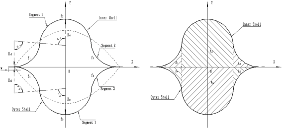
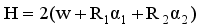
The double omega cross-section consists of an inner shell and an outer shell, where the inner shell is composed of geometric parameters Ri1, Ri2, αi1, αi2, and w, while the outer shell is composed of geometric parameters Ro1, Ro2, αo1, αo2, and w. To satisfy geometric coordination, with the subtended angle αi1=αi2 and αo1=αo2. The inner shell and outer shell arc lengths are specified as H, which was calculated using the following equation (1). All the geometric relationships were shown in Figure 1.
Figure 1. Geometric parameters of the cross-section of the double omega cross-section carbon fiber thin-walled tube structure.
(1)
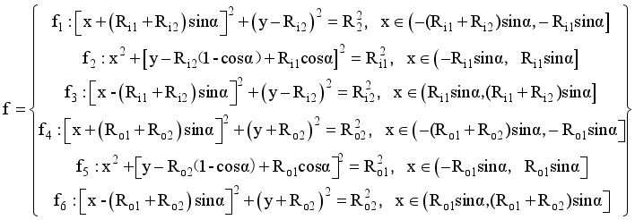
Inner Shell can be expressed by piecewise functions f1, f2, f3, Outer Shell can be expressed by piecewise functions f4, f5, f6 as well, which were calculated using the following equation (2).
(2)
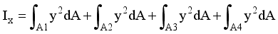
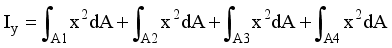
Meanwhile, area moment of inertia Ix and Iy were calculated using the following equations (3) and (4) respectively.
(3)
(4)
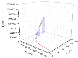
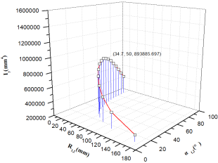
With the analytical model derived for the structure, a series of geometrical parameter studies were conducted to evaluate how geometric designs influence area moment of inertia Ix and Iy. Each shell of the section had two independent geometric parameters that could be varied, the subtended angle of both circular segments and the radius of either segment. To prevent kinks between the arcs and maintain tangent continuity, the subtended angle of both segments had to be identical. According to the arc length H=130 mm, the radius Ri1, Ri2, Ro1, Ro2 of segments remain equal on one hand.
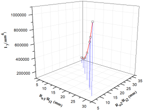
Figure 3. The area moment of Inertia Iy of symmetric section with equal radius with subtended angle varying.
As the subtended angle was varied from 5° to 90°, the radius Ri1,2, R01,2 of the inner shell and outer shell gradually decreased, and the cross-sectional moment of inertia Ix gradually increased. The area moment of inertia Ix reached a maximum when subtended angle was 90°, Ri1,2=Ro1,2=19.25 mm. The moment of inertia Iy of the cross-section increased firstly and then decreased. The area moment of inertia Ix reached a maximum when the subtended angle was 50°, Ri1,2=Ro1,2=34.7 mm; Ix and Iy were approximately equal when the subtended angle was 50°, Ri1,2=Ro1,2=24.75 mm; As shown in Figures 2 and 3.
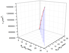
According to the arc length H=130 mm, the radius Ri1, Ro1 of segments remain equal, while the radius Ri2, Ro2 of segments remain unequal on the other hand.
As the radius Ri1 and Ro1 of the inner shell and outer shell increased, the radius Ri2 and Ro2 decreased, and the cross-sectional moments of inertia Ix and Iy gradually increased. The cross-sectional moments of inertia Ix>Iy, and the rate at which the cross-sectional moments of inertia Iy increased was greater than the rate at which Ix increased. As shown in Figures 4 and 5.
Figure 5. The area moment of Inertia Iy of symmetric section with unequal radius with subtended angle varying.
Optimal cross-sections were obtained by maximizing the area moments of inertia and torsional constants while maintaining bistability and satisfying volume requirements.
The geometric parameters of the carbon fiber thin-walled boom prepared are given as follows: H=130 mm, Ro1=Ri1=26.5 mm, Ro2=Ri2=12 mm, α=90°, w=4.5 mm.
Table 1. Geometric parameters of symmetrical radius section.
No
Ro1(mm)
Ro2(mm)
Ri1(mm)
Ri2(mm)
α(°)
w (mm)
1
26.5
12
26.5
12
90
4.5
3. Material and Methods
T300 level plain weave carbon fiber and E2314 epoxy resin were used to fabricate double omega carbon fiber thin-walled boom in this article. Table 1 shows the material description and properties of the thin-ply composites and adhesive that were used for the parametric analysis and boom fabrication. The shell layup and geometry were evaluated in the parametric analysis and are summarized in Table 2.
Table 2. Material properties of thin-ply composites and adhesive.
Label
Material Description
Fiber/ Resin
Lamina AW (g/m2)
Thickness t(mm)
PWc
Plain Weave Carbon Fiber
T300/ E2314
135
0.19
A
E2314 Film Epoxy
N/A
90
0.1
Table 3. Structure evaluated in parametric analysis.
Outer Shell Segment1
Outer Shell Segment2 and Web
Inner Shell Segment1
Inner Shell Segment2 and Web
h (mm)
w (mm)
[45 PWc]
[45 PWc]
[0/90 PWc]
[0/90 PWc]
130
4.5
Figure 6 shows three different process methods to preparing the double omega cross-section carbon fiber thin-walled tube structure, the methods include "Prepreg forming+ Post bonding" (PPD), "Co curing of prepreg for negative mould" (CPNM), "Co curing of prepreg for positive mould" (CPPM).
In terms of Prepreg forming+Post bonding ", inner shell and outer shell were cured by prepreg vacuum bagging technique (PVBT) separately first, and then the two shells were bonded together using same resin system adhesive without core mould. With regard to "Co curing of prepreg for negative mould", inner shell was cured by PVBT first, and then prepreg-outer shell was curing at the same time the two shells were bonded together using prepreg resin without core mould. For "Co curing of prepreg for positive mould", inner shell and outer shell were curing and bonded together at the same time using prepreg resin with core mould.
4. Results and Discussion
Figure 6 shows three structural components fabricated by three processes, looking from the appearance, there are no obvious differences.
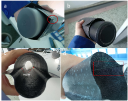
However the mechanical properties of carbon fiber structural component fabricated by "Co curing of prepreg for positive mould" is superior to those fabricated by the other two processes. The structural components fabricated by "Prepreg forming+ Post bonding", "Co curing of prepreg for negative mould" processes have high curling stiffness. During the curling, the cross-sections of them display quasi-circular. Micro cracks first appear in the bonding area, and the cracks propagate and brittle fracture occurs. The structural components can be curled even once. Compared with the structural components fabricated by "co curing of positive mould prepreg" process, have low curling stiffness. During the curling, the cross-sections of them display circular, there were no microcracks in the entire structural area. They can be curled multiple times and display good fatigue performance, as shown in the following Figure 7.
Figure 7. (a) Cracks occur in components fabricated by "Prepreg forming+ Post bonding " and "Co curing of prepreg for negative mould" while curling. (b) Curled component fabricated by "co curing of positive mould prepreg".(c) Resin rod occur inside the components fabricated by "Prepreg forming+ Post bonding " and "Co curing of prepreg for negative mould" along the bonding transition area (d) No resin rod occur inside the components fabricated by Co curing of prepreg for positive mould".
First, Inner shell and outer shell were fabricated at the beginning of "Prepreg forming+Post bonding", and then the two shells were bonded to form double omega carbon fiber thin-walled booms. Due to the pre curing of the inner shell and outer shell, the local stiffness of the bonding area is high. The bonding area of the inner shell and outer shell have poor adhesion with the core mould, resulting in forming gaps and adhesive columns easily. Additionally, the resin system of the prepreg is different from that of the adhesive, which can easily cause stiffness discontinuity of the component.
The structural components fabricated by "Co curing of prepreg for negative mould" are similar to those fabricated by "Prepreg forming+Post bonding". There is resin in the transition area of the inner shell and outer shell bonded, forming adhesive columns on the inner wall that cannot be completely removed, causing a sudden change in local stiffness. During the curling process, the local stress level exceeds the allowable stress of the material, resulting in cracks until failure.
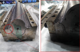
As for "Co curing of prepreg for positive mould", a metal core mould is used to occupy the bonding transition area between the inner shell and the outer shell. Under the condition of prepreg state, inner shell and outer shell are fully bonded to the core mould without any gaps, preventing the resin in the cured layer from flowing into the bonding transition area between inner shell and outer shell, and no adhesive column is formed. There is no sudden change in stiffness and no cracks and abnormal sounds during curling, as shown in the following Figure 8.
Figure 8. Close-up for inner shell and outer shell bonded during "co curing of positive mould prepreg".
In summary, the structural components fabricated by "Co curing of prepreg for positive mould" have good mechanical and curling performance.
5. Conclusion
1) Assuming that the arc length H remains constant and Ri1,2=Ro1,2, subtended angle increases, while the cross-sectional moment of inertia Ix gradually increases, Iy increases firstly and then decreases. As Ri1 &Ro1 increase and Ri2 &Ro2 decrease, the cross-sectional moments of inertia Ix and Iy gradually increase.
2) The mechanical properties of carbon fiber structural component fabricated by "Co curing of prepreg for positive mould" is superior to those fabricated by "Prepreg forming+Post bonding" and "Co curing of prepreg for negative mould".
3) Subsequently, curling experiments and researches will be conducted on the structural components fabricated by "co curing of positive mould".
Abbreviations
PVBT
Prepreg Vacuum Bagging Technique
PPD
Prepreg Forming+ Post Bonding
CPNM
Co Curing of Prepreg for Negative Mould
CPPM
Co Curing of Prepreg for Positive Mould
Author Contributions
Fanyi Meng: Data curation, Project administration, Validation, Writing – original draft, Writing – review & editing
Funding
The funding for this research came from the company independent project (CCACMKY23-05).
Conflicts of Interest
No potential competing interest was reported by the authors.
References
[1]
J. S Dai, M. Zoppi and X. Kong (eds) Advances in Reconfigurable Mechanisms and Robots1, Springer-Verlag, London, 2012.
[2]
H. H. Armstrong, R. R. Johnson, “Organic & Metal Matrix Composites for Spacecraft Applications”, SAMPE Quarterly, 1978.
[3]
J. M. Fernandez, “Advanced Deployable Shell-Based Composite Booms for Small Satellite Applications including Solar Sail”, 4th International Symposium on Solar Sailing. Kyoto, Japan, 17-20 Jan 2017.
[4]
Crouch, D. S., Mars Viking Surface Sampler Subsystem, 25 th Conference on Remote Systems Technology, 1977.
[5]
Aguirre-Martinez, M. A., Bureo-Dacal, R., Del Campo, F., Fuentes, M., The CTM family of Masts and the CTM Engineering Model, 3 rd European Space Mechanisms & Tribology Symposium, Madrid, Spain, 1987.
[6]
NASA Space Technology Mission Directorate, Game Changing Development Program,
Armstrong H. H., Johnson R. R., Organic & Metal Matrix Composites for Spacecraft Applications, SAMPE Quarterly, 1978.
[8]
B. B. Rennie, "New Closed Tubular Extendible Boom", 2nd Aerospace Mechanisms Symposium, ed: Herzl, G. G. JPL TM 33-355, pp. 163-170, 1967.
[9]
Herbeck, L., et al., Development and Test of Deployable Ultra-Lightweight CFRP-Booms for a Solar Sail, European Conference on Spacecraft Structures, Materials, and Mechanical Testing, Noordwijk, The Netherlands, 2000.
[10]
Geppert, U., et al., The 3-step DLR-ESA Gossamer Road to Solar Sailing, Advances in Space Research, Vol. 48, 1695-1701, 2011.
[11]
Hillebrandt, M., et al., The Boom Design of the De-Orbit Sail Satellite, 13 th European Conference on Spacecraft Structures, Materials and Environmental Testing, Braunschweig, Germany, 2014 (ESA SP-727, June 2014).
[12]
CARON R N. Copper Alloys: Properties and Applications [M] // Encyclopedia of Materials Science and Technology. Oxford: Pergamon, 2008.
[13]
LAURENCE W, JAMES H, ERWIN E. Evaluation of One Type of Foldable Tube: TMX-1187 [R]. NASA, 19.
[14]
A. J. Lee, J. M. Fernandez, “Mechanics of Bistable Two-Shelled Composite Booms“, 5th AIAA Spacecraft Structures Conference, AIAA Scitech 2018 Forum, Kissimmee, FL, 8-12 Jan. 2018.
[15]
J. M. Fernandez, et al., “An Advanced Composites-Based Solar Sail System for Interplanetary Small Satellite Missions“, 5th AIAA Spacecraft Structures Conference, AIAA Scitech 2018 Forum, Kissimmee, FL, 8-12 Jan. 2018.
Fanyi, M., Zaiwen, L., Weihui, S., Zhiwei, Z., Yanjun, C., et al. (2025). Designing and Fabrication of Double Omega Cross-section Carbon Fiber Thin-walled Boom. International Journal of Materials Science and Applications, 14(4), 128-133. https://doi.org/10.11648/j.ijmsa.20251404.12
@article{10.11648/j.ijmsa.20251404.12,
  author = {Meng Fanyi and Lin Zaiwen and Shang Weihui and Zou Zhiwei and Cao Yanjun and Qin Chuang},
  title = {Designing and Fabrication of Double Omega Cross-section Carbon Fiber Thin-walled Boom
},
  journal = {International Journal of Materials Science and Applications},
  volume = {14},
  number = {4},
  pages = {128-133},
  doi = {10.11648/j.ijmsa.20251404.12},
  url = {https://doi.org/10.11648/j.ijmsa.20251404.12},
  eprint = {https://article.sciencepublishinggroup.com/pdf/10.11648.j.ijmsa.20251404.12},
  abstract = {With the rapid development of aerospace fields such as deep space exploration, satellite communication, and remote sensing, increasingly stringent performance requirements have been imposed on spacecraft platforms and their payloads. On one hand, there is a demand for deploying large-scale, high-precision, and multi-functional structures in harsh space environments (e.g., large antennas, solar arrays, telescope shields, and truss platforms). On the other hand, constrained by the fairing space and payload mass limitations of launch vehicles, these large structures must be kept in a highly compact folded or rolled state during launch, then reliably and accurately deployed in orbit while maintaining required stiffness and surface stability. Traditional metal structures face bottlenecks in achieving high storage ratios (storage volume/unfolded volume) and large-scale lightweight design. In this context, the deployable structure of composite materials has emerged as a promising solution, with the with the double omega-section carbon fiber thin-walled boom gaining attention as a novel space deployable structure. In this study, the geometric dimensions of the double omega cross-section were optimized, and the relationship between the cross-sectional moment of inertia and geometric parameters was established through geometric parameter transformation. Additionally, three distinct fabrication processes for the double omega-section carbon fiber thin-walled booms were proposed and discussed.},
 year = {2025}
}
TY  - JOUR
T1  - Designing and Fabrication of Double Omega Cross-section Carbon Fiber Thin-walled Boom

AU  - Meng Fanyi
AU  - Lin Zaiwen
AU  - Shang Weihui
AU  - Zou Zhiwei
AU  - Cao Yanjun
AU  - Qin Chuang
Y1  - 2025/07/30
PY  - 2025
N1  - https://doi.org/10.11648/j.ijmsa.20251404.12
DO  - 10.11648/j.ijmsa.20251404.12
T2  - International Journal of Materials Science and Applications
JF  - International Journal of Materials Science and Applications
JO  - International Journal of Materials Science and Applications
SP  - 128
EP  - 133
PB  - Science Publishing Group
SN  - 2327-2643
UR  - https://doi.org/10.11648/j.ijmsa.20251404.12
AB  - With the rapid development of aerospace fields such as deep space exploration, satellite communication, and remote sensing, increasingly stringent performance requirements have been imposed on spacecraft platforms and their payloads. On one hand, there is a demand for deploying large-scale, high-precision, and multi-functional structures in harsh space environments (e.g., large antennas, solar arrays, telescope shields, and truss platforms). On the other hand, constrained by the fairing space and payload mass limitations of launch vehicles, these large structures must be kept in a highly compact folded or rolled state during launch, then reliably and accurately deployed in orbit while maintaining required stiffness and surface stability. Traditional metal structures face bottlenecks in achieving high storage ratios (storage volume/unfolded volume) and large-scale lightweight design. In this context, the deployable structure of composite materials has emerged as a promising solution, with the with the double omega-section carbon fiber thin-walled boom gaining attention as a novel space deployable structure. In this study, the geometric dimensions of the double omega cross-section were optimized, and the relationship between the cross-sectional moment of inertia and geometric parameters was established through geometric parameter transformation. Additionally, three distinct fabrication processes for the double omega-section carbon fiber thin-walled booms were proposed and discussed.
VL  - 14
IS  - 4
ER  -
 (1)
(1)  (2)
(2)  (3)
(3)  (4)
(4)